Keywords
5G communication systems; Channel modelling requirements; Channel
models; Beyond 5G communication systems
Introduction
The fifth generation (5G) mobile communication technology
supports people to access and share data with various scenarios,
with very high speed and very low latency [1]. Compared to the
current fourth generation (4G) technology, the system capacity
is 1000 times, the data rate is 100 times, the energy efficiency
is 10 to 100 times and the spectral efficiency is 3 to 5 times
improved [2,3]. mmWave is one of the most significant and most
promising technologies for 5G systems [4]. Different frequency
bands from 24 GHz to 86 GHz in mmWave band are defined for
5G communication systems by International Telecommunication
Union (ITU) in World Radio Communications Conference (WRC) in
2019 [5], in which 24.25-27.5 GHz and 31.8-33.4 GHz can be the
primary choice for 5G wireless access. Until now there are some
channel measurements and modelling work available at 24.25-
27.5 GHz, however, there are not enough results at 31.8-33.4 GHz
as far as we know which is why we concentrate on 32 GHz channel
in this study. Millimeter wave communications can easily provide
several gigabit data rates per second by the virtue of its huge
bandwidth. If small cells with a radius of 100 to 200 m are utilized,
mmWave communication can provide good performance without
additional losses [6]. In order to tackle the high path loss, another method is beamforming that can be obtained using massive
multiple input, multiple output (MIMO) technology. The working
principle of MIMO technology is, an antenna array with high gain
can transmit signals to desired directions or receive signals from
the desired direction so that signals can transfer around obstacles
and compensate for high path loss [7]. In addition, the massive
MIMO provides better capacity and better reliability compared to
MIMO [8,9]. It is predicted that 5G technologies will provide good
performance both under various network structures and between
various devices, for instance vehicle to vehicle or device to device
(V2V/D2D) communications, moving networks or multihop
networks. Moreover, 5G technologies should operate under a
wide variety of scenarios, including rural, suburban, urban and
indoor environments. The aforementioned technologies can be
used to model channel in 5G mobile communications, but there
are several requirements:
• Range of frequency: The new 5G channel model to be proposed
should be able to operate in a wide frequency range from 500
MHz to 100 GHz. In terms of interoperability with other mobile
communication generations (i.e., 3G, 4G), the channel model
above 6 GHz should be able to work with the channel model
below 6 GHz.
• Wide Bandwidths: The new 5G channel model to be designed
should be able to support ultra-wide bandwidth from 250 MHz
to 2 GHz.
• Wide variety of scenarios: The new 5G channel model to be
offered should be able to bolster a wide variety of scenarios such
as rural, suburban, urban and indoor environments.
• Three-Dimensional (3D) Modelling: A comprehensive 3D
model should be produced including accurate and reliable 3D
propagation modelling and 3D losses modelling in the new 5G
channel model to be presented.
• D2D/V2V Scenarios: In these scenarios, both the transmitting
antenna and the receiving antenna have small dimensions, so the
antennas are subject to interaction with numerous scatterers.
The most complex part in D2D or V2V channel models is that they
are moving on both sides. The speeds of the two sides relative to
each other and to be in different environments cause additional
Doppler frequency shift and non-stationary channels [10,11].
Considering the above, it is seen that the D2D/V2V channels are
very different from the cellular channels.
• Mobility: The new 5G channel model to be offered should
be able to support the high-speed train scenario with a speed
over 300 km/h. The channel model should be able to provide
information about some of the characteristics of high-mobility
channels, such as Doppler frequency and non-stationary.
Despite there are many studies on 5G channel modelling and
measurement, there are almost no number surveys about
5G channel modelling and measurement. Moreover, most
of the studies on 5G channel modelling and measurements
have focused on specific subjects. For instance, mmWave
communications [12], MIMO communications [13,14], and V2V
communications [15-17]. In all the studies mentioned, there are
deficient aspects related to 5G channel modelling. According to
the results obtained from the literature review, there is a lack of
survey study which includes 5G channel modelling, the channel
models developed by various standardization organizations and
channel modelling for beyond 5G systems. This paper aims to fill
the gap in the literature. The following contributions are aimed
with this study:
• The most important channel measurement models in the
literature were examined in terms of applications, frequency
bands and scenarios. New propagation mechanisms were
considered and discussed.
• Various scenarios were presented for 5G channel models.
Modelling structures were expressed and compared extensively
for each scenario.
• In channel modelling, research directions for 5G and next
generation mobile communication technologies were predicted.
The organization of the continuation of this study is as follows.
In the second section, 5G channel models made by various
standardization organizations are presented. In the third section, future research aspects of 5G and beyond 5G technologies are
mentioned. Finally, in the fourth section, the results obtained are
reported.
Methodology
5G channel models of standardization
organizations
In this section we will describe nine channel models. These channel
models are; 3GPP [18], IEEE 802.11ay [19], COST 2100 [20,21],
QuaDRiGa [22,23], MiWEBA [24,25], METIS [26], mmMAGIC
[27], IMT-2020 [28] and the more general 5G channel model
(MG5GCM) [29]. All other channel models except IEEE 802.11ay
and MiWEBA channel models are accepted as Geometry Based
Scotastic Models (GBSMs). The development of other channel
models is based on WINNER II and the Spatial Channel Model
(SCM). The Grid-Based GBSM (GGBSM) used in the mmMAGIC
and 5GCMSIG channel models was first proposed in the METIS
channel model. The GGBSM was developed to supply a spatially
consistent and smooth time evolution simulations. The mapbased
approach, also known as deterministic channel modelling,
was proposed by METIS. The map-based approach was improved
basis on a 3D geometrical environment to supply realistic,
reliable and accurate channel data. Combination of deterministic
channel modelling and stochastic channel modelling, which is
called hybrid channel modelling was first introduced by 3GPP
and METIS, and then adopted by IMT-2020. The hybrid model has
advantages such as providing a scalable and flexible simulation,
ensuring a harmony between complexity and accuracy. In
addition to the hybrid model, the IMT-2020 offers an extended
module taking into account the Time-Spatial Propagation (TSP)
model [30]. This proposed new method was used to obtain
channel parameters by considering environment parameters
such as building height, street width as an alternative to other
channel models. In consideration of the quasi-optical properties
of mmWave band, Quasi-Deterministic (Q-D) modelling method
combining stochastic method and deterministic method was
proposed by IEEE 802.11ay and MiWEBA. It was observed that
the Q-D method exceeds the difficulties encountered in channel
modelling for outdoor environment at 60 GHz band.
3GPP channel model: The 3GPP channel model has been updated
several times, but the most up-to-date 3GPP channel model is
the 3GPP TR38.901 [18], which is commonly used with a 3D wide
range of additional modelling components.
Oxygen absorption between the 53 GHz and 67 GHz was
modelled as a function of 3D distance between the transmitter
and receiver, delay, central frequency by 3GPP. In the 3GPP
channel model, intra-cluster powers and delays were unequally
determined, moreover high spatial and temporal stability were
achieved for large antenna arrays and large bandwidths. In order
to have different angle, power and delay for each Multipath
Component (MPC), the offset angles of the rays were randomly
generated in the cluster. In addition, the number of rays in the cluster at a specified range were determined in light of a set of
parameters; array size, intra-cluster delay propagation and intracluster
angular propagation. Measurements in millimeter wave
frequencies indicate that, the overlap of the Line of Sight (LoS)
rays and the reflected rays from the ground induces an important
fading effect. The rays reflected from the ground by the geometric
method are modelled separately from the LoS components
and the Non-Line of Sight (NLoS) components. The interaction
of the waves having small wavelengths with the propagation
environment indicates that the millimeter wave channels depend
on the frequency [31]. Correlation modelling was supported in
the 3GPP channel model, for multiple frequencies in the same
scenario. In addition, parameters were modelled depending on
the frequency, such as cluster power, angular propagation and
delay propagation.
The 3GPP offered both a stochastic model and a map-based
hybrid channel model. This map-based model is a combination
of a deterministic component and a stochastic component.
The deterministic component was constitute on a digital map
by using the Ray Tracing (RT) method and taking into account
effects of materials and environmental structures [26]. Stochastic
component was improved from 3GPP stochastic modelling
method. In the case of massive MIMO and large bandwidth, the
entire bandwidth is divided into multiple sub-bands that are
not more than the ratio of light speed to the maximum antenna
aperture (c/D), and then sub-bands are modelled respectively
one by one.
The channel model in a question, capable of simulating spherical
waves in massive MIMO, non-stationary antenna array and
dual mobility, also takes into account atmosphere attenuation,
blockage effects and spatial consistency in mmWave bands.
Furthermore, the parameterization study for four scenarios such
as indoor office, rural macro cell (RMa), Urban Macro cell (UMa)
and street canyon was completed.
IEEE 802.11ay channel model: The IEEE 802.11ad channel
model [32], improved for the 60 GHz band (i.e. 57-68 band)
was updated to become IEEE 802.11ay channel model [19]. The
Quasi-Deterministic (Q-D) channel modelling approach used
and developed in the MiWEBA model [24] has been adopted.
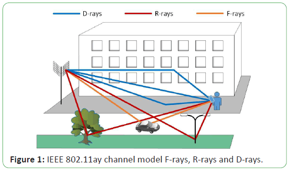
F-rays, R-rays and D-rays form multipath of the IEEE 802.11ay
channel model. F-rays originate from moving objects like vehicles
and occur only for short periods of time relatively. F-rays were
modelled in stochastic manner, but with a shorter existence
time. Relatively poor rays resulting from reflections on objects
(random or small) whose position is unpredictable are R-rays.
R-rays also were modelled stochastic manner following specific
distributions similar to F-rays. The arrival time of the R-rays
follows a Poisson process, the phases were uniformly distributed,
and the amplitudes were modelled as Rayleigh distribution [33].
As shown in Figure 1 [19], such as rays reflected from the ground,
LoS rays, and other rays reflected from important objects in the
scenario relatively strong rays are D-rays. D-rays are modelled
depending on the scenario.
Figure 1: IEEE 802.11ay channel model F-rays, R-rays and D-rays.
The IEEE 802.11ad channel model, which focuses on indoor
scenarios such as living room, cell environment and conference
hall, is a Single Input Single Output (SISO) model. The IEEE
802.11ay channel model was obtained by adding MIMO usage
to the IEEE 802.11ad channel model. Measurement results and
RT simulations show that the model can be used more scenarios,
such as open space and street canyon. In many outdoor scenarios,
D-rays are composed of two components: the beam reflected
from the ground and the LoS beam. In addition, the model cannot
support high mobility and massive MIMO.
COST 2100 channel model: The COST 2100 channel model
focusing on frequency bands below 6 GHz was improved in the
light of the COST 259 [34] and the COST 273 channel models
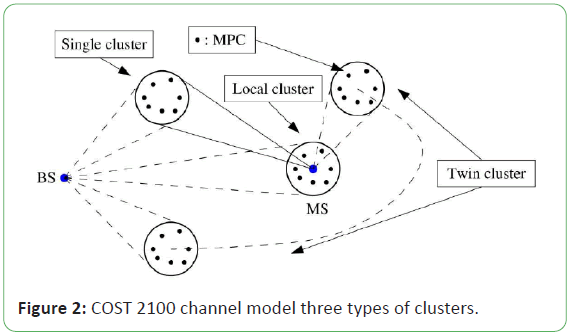
[35]. In the COST 2100 channel model, there are three types of
clusters including twin clusters, single bounced clusters and local
clusters as shown in Figure 2 [20]. The Base Station (BS) and the
Mobile Station (MS) must be defined in order to determine the
locations of the twin clusters. The delay and angular parameters
on both the BS and the MS side are required to determine the
location of the single bounced clusters. Twin clusters and single
bounced clusters are located far from the BS and MS. However
local clusters are located around the BS or MS. It is assumed that
all clusters in COST 2100 are shared by all links and distributed
in fixed locations in the propagation environment. According
to the cluster distributions and the geometry of their locations
the parameters such as power, delay and angle were acquired.
That is contrarily to the 3GPP/WINNER model, since clusters exist
indirectly. The cluster parameters were designated indirectly
according to clusters locations and propagation environment.
Figure 2: COST 2100 channel model three types of clusters.
The concept of Visibility Region (VR) in the COST 273 is also
included in the COST 2100. The VRs were described with circular
regions of the same size, equally distributed in the azimuth plane.
VRs point out whether a cluster is visible by the MS. In other
words, they indicate the extent to which a channel contributes
to its realization and whether a cluster is active. Each VR
corresponds to a certain cluster, and VRs may impose. The cluster
corresponding to the MS changes as the mobile station enters
and exits different visibility zones that are causing non-stationary
channel simulations.
Receivers in closely configuration can see similar environments
by taking advantage of certain locations of clusters. Therefore,
the model is spatially consistent and able to be simulated in a
realistic and natural way. The COST 2100 model is based on the
fixed locations of the clusters in order to obtain the spherical
wave fronts easily. It also promotes long time or long-distance
simulations and smooth time evolution. The COST 2100 has a
disadvantage that the propagation environments defined by the
three types of clusters are complex, besides to the mentioned
advantages. Furthermore, obtaining and verifying cluster
properties through channel measurements leads to relatively
difficulties. While propagation environments can be modelled in
3D, visibility zones cannot be modelled in 3D and are still modelled
in 2 dimensions. These above-mentioned disadvantages restrain
the use of the COST 2100 channel model.
QuaDRiGa: QuaDRiGa is a GBSM which was developed from the
WINNER+ channel model and also supports many new features
[22]. One of the innovations in the latest version of QuaDRiGa is
the production process of the correlated Large-Scale Parameters
(LSPs) and supports the frequency range of 0.45 to 100 GHz. In
QuaDRiGa channel model, the correlated maps were produced
with a 2D map was produced that includes all locations of the
receivers. The 2D maps are filtered besides in vertical and horizontal
directions, also in diagonal directions, in order to achieve a
proper location evolution LSPs. This process was performed with
two additional Finite Impulse Response (FIR) filters according to
the correlation distance of the LSPs [22,23]. The model supports
smooth time evolution by dividing the receiver trajectory into
many parts for a long time or distance. A part is admitted to be
a time interval, in which the wide-sense stationary is valid [36]
and LSPs do not change significantly. A certain number of clusters
were produced independently in each part and developed over
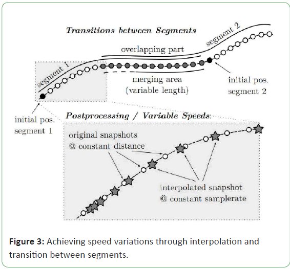
time, according to geometric relationships. QuaDRiGa, utilizing
superimposing regions, combines independent parts with long
time sequence channel coefficients as shown in Figure 3 [22]. This
causes the old clusters to ramp-down and the new clusters rampup
by following a sinus square function. When the MS moves
with acceleration, the channel can be modelled by QuaDRiGa
with improperly interpolating the channel coefficients. Moreover, Although QuaDRiGa current version cannot support scenarios
where both the transmitter and the receiver are moving, it can
support multi-hop networks, multi-cell, multi-user, massive
MIMO antennas and 3D antenna modelling. Moreover, the model
uses only the WINNER-like modelling structure. QuaDRiGa must
achieve a reliable, scalable and flexible simulation and support
more advanced channel properties, therefore it must take
advantage of other modelling approach such as a map-based
model.
Figure 3: Achieving speed variations through interpolation and
transition between segments.
MiWEBA channel model: 57 GHz and 66 GHz frequency range
(i.e., 60 GHz band) is supported by MiWEBA channel model.
In mmWave propagations, low-order reflection components
and LoS components compose the majority of the receiving
power that was observed through measurements [6,32,37,38].
Diffraction components power is relatively insignificant. In
mmWave bands propagation channels demonstrate quasi-optical
properties. Therefore a Q-D approach was utilized in MiWEBA
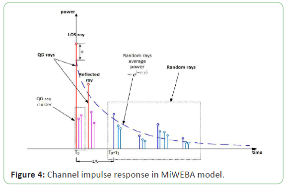
channel model. The channel impulse response of the MiWEBA
model is obtained by overlapping R-rays and D-rays as shown in Figure 4 [24]. Reflected from objects such as lampposts, trees
and cars weak rays are R-rays. These rays are obtained from the
RT simulation results or channel measurement data, as random
clusters with stated statistical parameters. D-Rays were modelled
with a deterministic method according to the geometry of the
environment and these rays compose most part of the received
power.
Figure 4: Channel impulse response in MiWEBA model.
Several new communication technologies, such as D2D
communications, massive MIMO communications and beam
forming are supported by MiWEBA channel model. Model
also supports time evolution and evaluates the diffusion rate
according to the specular reflection components. The first
version of the model can be used for only three scenarios (D2D
scenarios, backhaul and outdoor access) in the 60 GHz band. In
MiWEBA channel model, dynamic modelling capability is still very
restricted and D-Rays were acquired on a certain propagation
environment using the RT method.
METIS channel model: In the METIS channel model, a stochastic
model, a map-based model and a hybrid model [26] with their
combination are used, to support scalable and flexible channel
modelling. The stochastic model supports the frequency range
of up to 70 GHz, the map-based model supports up to 100 GHz
frequency range.
Based on random shadowing objects and using a simplified
3D geometric definition of a propagation environment and
based on RT simulation were achieved map-based model. The
model, considered propagation structures like blockage diffuse
scattering, diffraction and specular reflection. In order to
decrease complexity or to increase accuracy diffuse and specular
components were taken into account or not. The map-based
model meets most of the requirements of the 5G channel model.
In addition, it is suitable for application of various 5G technologies
such as beam forming, massive MIMO communications, mmWave
communications, so it is a significant candidate as 5G channel
model.
The METIS channel model uses the stochastic model that is a
GBSM improved from the WINNER/3GPP model. In the D2D or
V2V scenarios, a six-dimensional (6D) correlation map of LSPs
is used when both the transmitter and the receiver are moving.
This map creates spatially consistent LSPs [39,40] and leads to
high computational complexity. A new approach was suggested
including a sum of sinusoidals to produce spatially consistent
large-scale parameters by METIS model, which provides more
efficient memory utilization and computation than conventional
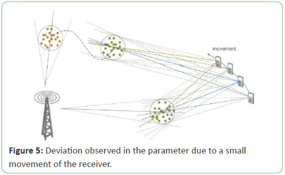
methods. In the stochastic model shown in the Figure 5 [26], an
idea for spherical wavefront and time evolution was proposed.
The clusters locations were kept constant according to parameters such as angles and delays. So, parameter deviations can be
computed based on geometry.
Figure 5: Deviation observed in the parameter due to a small
movement of the receiver.
In the first METIS channel models [41], as well as the map-based
model and stochastic model, grid-based GGBSM was offered for
long time or distance simulations and spatial consistency was
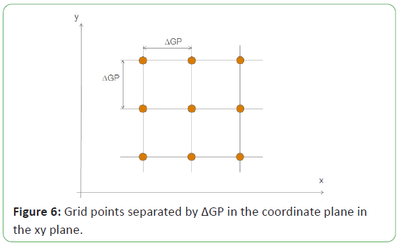
obtained. LSPs and Small-Scale Parameters (SSPs) in GGBSM
were randomly generated for each predefined grid as shown
in Figure 6 [41], and were obtained on the basis of a 2D map
covering all receiver locations in the GGBSM. The interpolation
of the parameters in the four closest grids gives the parameters
in the actual user locations. Deviations in LSPs and SSPs could be
followed up depending on the geometry, and the locations of
the clusters were specified by path angles and delays as shown
in Figure 5.
Figure 6: Grid points separated by ΔGP in the coordinate plane in
the xy plane.
Scenarios such as V2V communications, D2D communications,
shopping mall, indoor, urban micro cell (UMi) and dense UMa
cell are supported by METIS channel model and it also supports
scalable and flexible channel modelling. It is presumed that the
map-based model is simpler than the stochastic model. Moreover
map-based model is derived from a simplified 3D digital map that
requires truing with measurements.
mmMAGIC channel: QuaDRiGa and the 3GPP (3GPP TR36.873)
[42] 3D channel modelling approach was adopted by mmMAGIC
channel model. Through the mmMAGIC channel model,
measurements was performed in scenarios such as outdoor
environment to indoor environment (O2I), open square in UMi,
street canyon in UMi, airport and indoor office. In the mmMAGIC
channel model, several new modelling methods were offered
in order to operate in mmWave bands. LSPs were modelled, according to the measurement results, as frequency dependent.
The rays and clusters were modelled according to extended Saleh-
Valenzuela model [43], which defines both temporal and spatial
domains and LSPs were also modelled according to measurement
results as frequency dependent. Rays numbers and clusters
numbers in a cluster are modelled random variables. Moreover,
in the mmMAGIC channel model ground reflection and blockage
effects are taken into account.
It is estimated that model compensates majority of the 5G
channel modelling requirements. In addition model operates a
great bandwidth 2 GHz and large frequency range between 6 GHz
and 100 GHz. Scenarios are not supported yet where both the
transmitter and the receiver are mobile. Despite the mmMAGIC
channel model can cooperate with many advanced modelling
components, how to decrease the complexity of the model
and how to obtain a flexible combination of these modelling
components must be handled.
IMT-2020 channel model: The IMT-2020 channel model (28)
is a GBSM based on 3GPP TR36.873 channel model [42] and
the IMT-Advanced channel model [44]. The model supports
blockage modelling, large antenna array, spatial consistency, 3D
propagation modelling and large bandwidth in great frequency
range of up to 100 GHz. The IMT-2020 model was taken into
account gas absorption for mmWave bands. Furthermore it also
examined the effects of vegetation such as diffusely scattering
caused by leaves and diffracted caused by tree canopy. A ground
reflection model was presented in the IMT-2020 channel model
similar to 3GPP TR38.901 and the frequency dependence of the
channel was taken into account.
Two extended modules were offered that improve alternative
approaches for producing channel parameters by IMT-2020
channel model. One of the extended modules operates below 6
GHz band and it was based on the TSP model used in the IMT-Advanced
channel model. Environment-specific parameters like
BS height, building height and street width were considered. The
other one of the extended modules operates above 6 GHz band.
It was improved based on the map-based hybrid model of the
3GPP that supports a flexible, realistic and accurate simulation
utilizing a certain geometric environment. Simulations of both
the transmitter and the receiver are mobile cannot be supported
in the IMT-2020 channel model.
MG5GCM: Nowadays, the ability to perform specific
characteristics of key 5G communication scenarios such as
mmWave communications, V2V, high-speed train and massive
MIMO, a non-stationary 3D more general 5G channel model was
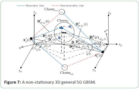
presented [29]. The presented model was improved according
to the Saleh Valenzuela and WINNER II as illustrated in Figure
7. Birth-death processes are modelled as the appearance and
disappearance of clusters on the time axis and array axis. In new
composed clusters, angles, powers and delays are randomly
produced according to specific distributions in each time instant.
Based on their geometrical relations, the parameters were
recreated for surviving clusters. In order to provide massive MIMO
communications, the spherical wave front was computed based
on the clusters physical location. Taking into account high spatial and temporal resolution needs of mmWave channel models,
the rays numbers inside of clusters were modelled as Poisson
distributed and the powers and delays of the rays inside of the
clusters were modelled in an unevenly. Moreover, to provide V2V
communications both on the transmitter and on the receiver side
Doppler frequencies were considered.
Figure 7: A non-stationary 3D general 5G GBSM.
In the MG5GCM channel model, a number of channel modelling
technologies such as intracluster delay propagation, spherical
wave front, and array-time evolution were combined. Majority
of 5G channel modelling necessities can be met and also can be
reduced computational complexity by model. By adjusting the
parameters correctly, the model is not only reduced to a variety
of simplified channel models but can also be adapted to various
communication scenarios. Nevertheless, the MG5GCM was
focused on omitted large-scale fading and small-scale fading. In
addition the model parameters should be subtracted from the
future channel measurements for different scenarios.
Comparison of 5G channel models: Several 5G channel models
such as 3GPP (TR38.901), QuaDRiGa, METIS, mmMAGIC,
5GCMSIG, IMT-2020 and MG5GCM utilized WINNER-like
framework. According to 5G channel modelling requirements,
additional modelling components were added to these models.
3GPP (TR38.901), METIS and IMT-2020 channel models used the
map-based hybrid channel model, in order to obtain a reliable,
scalable and flexible simulation. In IEEE 802.11ay and MiWEBA
channel model, combining a deterministic model which is based
on (Q-D) method and a stochastic method is used. Many of 5G
channel models promote a large range of frequencies from 0.45
GHz to 100 GHz. Exceptionally the IEEE 802.11ay and MiWEBA
channel model were focused on only on the 60 GHz band. In
order to model for mmWave channel, 3GPP TR38.901, IEEE
802.11ay, MiWEBA, mmMAGIC and IMT-2020 channel model
can be used. These models are map-based channel models that
take into account the effects of blockage and gas absorption,
and have accurate and realistic determinations on propagation
in mmWave bands. In addition, the MG5GCM bolsters the most
demanding four scenarios of 5G communication systems such as
mmWave communications, high-speed train communications,
V2V communications and massive MIMO communications. As
shown in Table 1 an extensive comparison of 5G channel models
was performed.
| Characteristic |
3GPP |
IEEE 802.11ay |
COST 2100 |
QuaDRiGa |
MiWEBA |
METIS |
mmMAGIC |
IMT-2020 |
MG5GM |
| Range of frequency (GHz) |
0.5-100 |
57-68 |
<6 |
0.45-100 |
57-66 |
up to 100 |
up to 70 |
6-100 |
0.5-100 |
- |
| Bandwidth |
10% of the center frequency |
2.64 GHz |
- |
1 GHz |
2.16 GHz |
10% of the center frequency |
100 MHz
(<6GH),
1 GHz at 60 GHz |
2 GHz |
100 MHz (<6 GHz), 10% of the center frequency (>6 GHz) |
- |
| Support mmWave |
ok |
ok |
none |
ok |
ok |
ok |
partly |
ok |
ok |
ok |
| Method of modeling |
GBSM,
map-based
hybrid model |
Q-D based model |
GBSM |
GBSM |
Q-D based model |
map-based |
stochastic |
GBSM, GGBSM |
GBSM, TSP,
map-based hybrid model |
GBSM |
| Modeling of blockage |
ok |
ok |
none |
none |
ok |
ok |
none |
ok |
ok |
none |
| Gas absorption |
ok |
ok |
none |
none |
ok |
ok |
none |
ok |
ok |
none |
| High mobility |
limited |
none |
ok |
ok |
none |
none |
limited |
ok |
limited |
ok |
| Dynamic modeling |
ok |
limited |
ok |
ok |
limited |
ok |
none |
ok |
ok |
ok |
| Support dual-mobility |
none |
ok |
none |
none |
ok |
ok |
limited |
none |
none |
ok |
| Spatial consistency |
ok |
none |
ok |
ok |
ok |
ok |
shadow fading only |
ok |
ok |
none |
| Support spherical waves |
none |
none |
none |
ok |
ok |
ok |
none |
ok |
none |
ok |
-: No information was found in the relevant papers.
Table 1: 5G channel models comparison.
Results and Discussion
Simulations of large-scale path loss model at 32
GHz in indoor office
In this section, we present an explanation of the path loss model
and scenario discussed in the simulation campaign. We utilized
Wireless Insite software from REMCOM Inc. for the simulation
campaign. Wireless InSite software can simulate complex urban,
indoor and rural environments using the ray tracing method and
provides efficient and accurate predictions of electromagnetic
propagation and communication channel characteristics.
Simulation software: Simulations were performed via Wireless
Insite 3.3.0.3 software. In the simulation environment, the
waveform was selected as sinusoid with center frequency 32
GHz, bandwidth 1 GHz and phase angle 0°. On the transmitter
side, omnidirectional antenna with a gain of 20 dBi, VSWR value
1, E-plane half-power beamwidth of 45° and input power of
25 dBm was used. On the receiver side, broadband directional
pyramidal horn antenna was used with a gain of 18.5 dBi, VSWR
value 1, and 3 dB beamwidth of 10° in azimuth and 11° elevation.
The antennas on both the transmitter side and the receiver side were vertically polarized. The continuous wave was transmitted
from the transmitter and the received power was recorded on
the receiving side. Shooting-and-Bouncing-Rays (SBR) method
was chosen as the ray tracing method and full 3-D model was
chosen as the propagation model in the simulation environment. Table 2 show the parameters used in the simulation environment.
| Parameter |
Configuration |
Units |
| Center frequency |
32 |
GHz |
| Bandwidth |
1 |
GHz |
| Transmission signal |
Continuous wave |
- |
| Transmitter and receiver antenna |
Omnidirectional and directional horn antenna |
- |
| Transmitter antenna power |
25 |
dBm |
| Transmitter antenna height |
2.3 |
m |
| Receiver antenna height |
1.6 |
m |
| Transmitter and receiver antenna polarization |
Vertical |
- |
Table 2: Channel parameters in the simulation environment.
Simulation scenario: We performed simulation campaigns in the
indoor office on 4th floor of the Engineering Faculty building,
University of Karabuk, Turkey. The simulation environment was a
well-known indoor office, floor and walls made of concrete, glass
windows, wooden furniture’s and doors. The transmitter antenna
was mounted 2.3 meters above the ground as in characteristic
indoor hotspots, and the receiver antenna was mounted 1.6
meters as in characteristic handsets. In the office, the transmitter
antenna was fixed, the receiving antenna was positioned in
6 different locations for simulations both LoS and NLoS. The
directional horn antenna on the receiver side was rotated in 10°
steps over the azimuth plane. Both omnidirectional antenna and
pyramidal horn antenna were vertically polarized in all simulation
tests.
The separation distance between the transmitter and receiver
varied from 1 m to 4 m. The simulations were carried out with 1
m steps from 1 m to 4 m under LoS conditions and at 1.8 m and
3.64 m under NLoS conditions. The simulations were performed
indoor office that is in the 4.88 m long, 2.80 in wide and 3.30
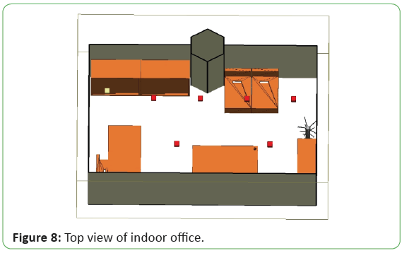
m high indoor office. The transmitter (yellow box) and receiver
positions (red boxes) and the office plan are seen in Figure 8. In
each of transmitter and receiver combinations, the receiver was
rotated over azimuth plane with 10° steps, elevation plane kept
constant at 0°. 36 different angles of arrival were obtained at each
receiver position with rotating 10° steps over 360° azimuth plane.
The transmitter antenna kept constant at 0° in both azimuth and
elevation plane.
Figure 8: Top view of indoor office.
We processed the received power for each receiver locations via the simulation software. The path loss was estimated through the
conversion of the power received at each point.
Analysis of large-scale path loss model: The attenuation of the
signals propagating in any environment over the distance is
estimated by large-scale path loss models. They are important
to design more accurate, reliable and efficient next-generation
communication systems. Estimating the dominant propagation
mechanisms in the indoor office environment is significant in
modelling the path loss for 5G communications. In this study,
large-scale path loss was modelled in office environments and
compared with other 5G channel models in office environments.
Path loss value in free space is calculated with the following
equation:

where d is the separation distance between transmitter and
receiver, f is the carrier frequency, c is the speed of light, G_t is
the gain of the transmitter and G_r is the gain of the receiver.
In this study, the model known as close-in (CI) was used to
improve the path loss model. The reference distance in free space
is accepted as 1 meter and the path loss intercept in CI model is
calculated as follows:

where f is the carrier frequency, c is the speed of light, n is the path
loss exponent, d is the separation distance between transmitter
and receiver in 3D space, d_0 is the reference distance in free
space and X_σ^CI is a random variable with zero mean Gaussian
random variable with a standard deviation σ in dB. The path loss
exponent (n) is determined using the minimum square error
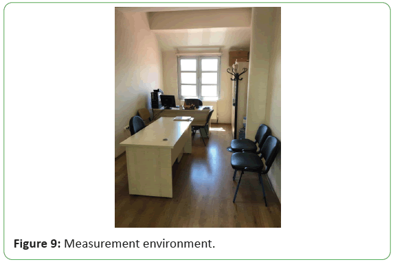
method. Measurement environment is shown in Figure 9.
Figure 9: Measurement environment.
In the simulations, the horn antenna at the receiver side is
rotated by 10° angular steps over the entire azimuth plane while
the elevation angle is 0°. Thus, the directional path loss model is
improved which is very useful for the beam forming technique in
future millimeter wave communication systems. The directional
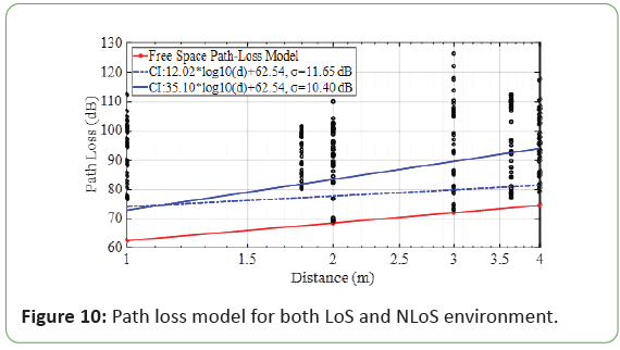
path loss for the LoS and NLoS simulation scenarios using the CI
method expressed in (1) is shown in Figure 10. The dashed blue
line represents the path loss according to the CI method in the
case of LoS, and the blue line represents the path loss according
to the CI method in the case of NLoS in Figure 10. The 36 black
marks in each column are 36 path loss values from 36 azimuth
angles while the elevation angle is 0°. The parameters of the path
loss model are listed in Table 3.
| Frequency (GHz) |
32 GHz* |
32 GHz in mmMAGIC** |
32 GHz in 3GPP TR 38.901*** |
| LoS |
NLoS |
LoS |
NLoS |
LoS |
NLoS |
| Path loss exponent |
1.2 |
3.51 |
1.38 |
3.69 |
1.73 |
3.83 |
| Intercept |
62.54 |
62.54 |
33.6 |
15.2 |
32.4 |
17.3 |
| σ |
11.65 |
10.4 |
1.18 |
8.03 |
3 |
8.03 |
Table 3: Comparison of the parameters in this study and open literature.
Figure 10: Path loss model for both LoS and NLoS environment.
The obtained path loss exponents are in good agreement with
the channel models such as 3GPP and mmMAGIC in the open
literature. The obtained parameters of intercept and are different
from 3GPP and mmMAGIC channel models, due to the channel
models use ABG path loss model and we use CI path loss model.
Future research aspects for 5G and beyond 5G
channel modelling
Still there are many disputes about the characteristics of future
channel models, except for the topics mentioned above. In future,
due to improving channel models, researches will concentrate
on that are working together with other modelling methods,
covering extremely large frequency bands, focusing on new
scenarios and more efficient. In order to model the channel in the
future, attractive bands will be Terahertz (THz) communication
and visible light communications, the attractive environments
will be the human body, underwater, underground and tunnel.
THz communication channel modelling: In the electromagnetic
spectrum, taking part between the mmWave and infrared wave,
electromagnetic waves ranging from 300 GHz to 10000 GHz, are
called THz waves. The THz band is considered a virgin field that
has not been exploited before [45]. Due to the advancement of
semiconductor device technology and the high data rate required
by the end user, the attention to THz communication technologies
is rapidly growth. The THz communication is predicted to support
high data rates of up to 100 Gbps with its great bandwidth [46].
The signals propagated in the THz band, owing to their high
frequencies can face with much greater atmospheric attenuation
and free space path loss than the signals propagated in lower
frequency bands [47]. Hence, THz systems will highly likely be used
together with beam steering techniques in indoor scenarios. The
number of developed THz channel models is very low, and THz
channel modelling is still in the initial phase. A GBSM proposed
to evaluate the performance of the THz channels at system level
and to explore their physical properties [48]. A THz channel
multi-ray model offered by means of RT methods considering the
components of diffracted, scattered, reflected and LoS [49]. It is
estimated that more THz channel models will be developed and
will be useful.
Visible light communication channel modelling: The visible light
band is considered another virgin field that has not been exploited
before. The visible light spectrum is taking part between 430
THz and 790 THz [50]. This range can be detected by the human
eye. Light Emitting Diode (LED) can be used as a transmitter in
visible light communication, thus providing both communication
and illumination at the same time. Visible light communication,
which has many attractive characteristics, can be a promising
solution considering the spectrum shortage in microwave bands. Compared to microwave channels, visible light communication
channels can demonstrate different features such as high
security, economical, energy saving and environmentally friendly
[2,51]. So far, few visible light communication channel models
have been improved. Developed deterministic models according
to the RT method proposed for visible light communications
channels [52,53]. Both the geometry-based single-bounced
channel model and the geometry-based multi-bounced channel
model are offered for visible light communication channels
[54,55]. However, a single-ring model is basis on the geometry-based
single-bounced channel model, and an ellipse model or
two-ring model is basis on the geometry-based multi-bounced
channel model. Three-order reflections were taken into account
in the geometry-based multi-bounced channel model. A group
of researchers was proposed a model of path loss channel
for the visible light communication in the underground mine
scenario [56]. A detailed review of the channel modelling and
measurements in optical wireless communication systems was
conducted. It is estimated that more visible light communication
channel models will be developed and will be useful.
Conclusion
In this study, an extensive survey of important issues presents
in 5G channel modelling and future research aspects beyond
5G. 5G channel modelling requirements have been investigated.
The channel models developed by various standardization
organizations for the scenarios that are expected to be used
in 5G technology such as mmWave communication, V2V
communication and massive MIMO communication have
been examined and debated. The channel models covering 5G
scenarios are compared. Additionally the path loss is modelled
in an indoor office environment for 5G communication in the
millimeter waveband. The obtained path loss model is compared
with the other path loss models in the open literature. Future
research aspects for 5G systems and beyond 5G systems have
been summarized. 5G channel models must be simulated
through wireless propagation channels, in various scenarios, in
various network topologies and in a wide range of frequencies.
In 5G systems, hybrid channel model method or multiple
channel modelling method should be used rather than only one
modelling method. Thus, the challenges faced in 5G systems can
be overcome and a good balance can be obtained between the
complexity and the accuracy of the model.
References
- Boccardi F, Heath RW, Lozano A, Marzetta TL, Popovski P (2014) Five disruptive technology directions for 5G. IEEE Commun Mag 52: 74-80.
- Wang CX, Haider F, Gao X, You XH, Yang Y, et al. (2014) Cellular architecture and key technologies for 5G wireless communication networks. IEEE Commun Mag 52: 122-30.
- Fallgren M, Timus B (2013) Scenarios, requirements and KPIs for 5G mobile and wireless system. METIS Deliv D 1: 1.
- Roh W, Seol JY, Park J, Lee B, Lee J, et al. (2014) Millimeter-wave beam forming as an enabling technology for 5G cellular communications: Theoretical feasibility and prototype results. IEEE Commun Mag 52: 106-13.
- World radio communication conference (WRC-19). International Telecommunication Union-ITU 2020, Sharm el-Sheikh, Egypt, 2019.
- Rappaport TS, Sun S, Mayzus R, Zhao H, Azar Y, et al. (2013) Millimeter wave mobile communications for 5G cellular: It will work. IEEE access 1: 335-49.
- Kutty S, Sen D (2015) Beamforming for millimeter wave communications: An inclusive survey. IEEE Commun Surv Tutor 18: 949-73.
- Larsson EG, Edfors O, Tufvesson F, Marzetta TL (2014) Massive MIMO for next generation wireless systems. IEEE Commun Mag 52: 186-95.
- Rusek F, Persson D, Lau BK, Larsson EG, Marzetta TL, et al. (2012) Scaling up MIMO: Opportunities and challenges with very large arrays. IEEE Signal Process Mag 30: 40-60.
- Tan I, Tang W, Laberteaux K, Bahai A (2008) Measurement and analysis of wireless channel impairments in DSRC vehicular communications. In 2008 IEEE International Conference on Communications: 4882-8.
- Renaudin O, Kolmonen VM, Vainikainen P, Oestges C (2013) Wideband measurement-based modeling of inter-vehicle channels in the 5-GHz band. IEEE Trans Veh Technol 62: 3531-40.
- Rappaport TS, MacCartney GR, Samimi MK, Sun S (2015) Wideband millimeter-wave propagation measurements and channel models for future wireless communication system design. IEEE Trans Commun 63: 3029-56.
- Wang CX, Wu S, Bai L, You X, Wang J, et al. (2016) Recent advances and future challenges for massive MIMO channel measurements and models Sci China Inf Sci 59: 1-6.
- Zheng K, Ou S, Yin X (2014) Massive MIMO channel models: A survey. Int J Antennas Propag, 2014.
- Matolak DW (2008) Channel modeling for vehicle-to-vehicle communications. IEEE Commun Mag 46: 76-83.
- Molisch AF, Tufvesson F, Karedal J, Mecklenbrauker CF (2009) A survey on vehicle-to-vehicle propagation channels. IEEE Wirel Commun 16: 12-22.
- Wang CX, Cheng X, Laurenson DI (2009) Vehicle-to-vehicle channel modeling and measurements: Recent advances and future challenges. IEEE Commun Mag 47: 96-103.
- 5G; Study on channel model for frequencies from 0.5 to 100 GHz, (3GPP TR 38.901 version 14.0.0 Release 14), European Telecommunications Standards Institute, 2017.
- Maltsev A, Pudeyev A, Lomayev A, Bolotin I (2017) Channel Models for IEEE 802.11 ay. IEEE doc: 802-11.
- Liu L, Oestges C, Poutanen J, Haneda K, Vainikainen P, et al. (2012) The COST 2100 MIMO channel model. IEEE Wirel Commun 19: 92-9.
- Verdone R, Zanella A (2012) Pervasive mobile and ambient wireless communications: COST action 2100. Springer, 2012.
- Jaeckel S, Raschkowski L, Borner K, Thiele L (2014) QuaDRiGa: A 3-D multi-cell channel model with time evolution for enabling virtual field trials. Int J Antennas Propag 62: 3242-56.
- Jaeckel S, Raschkowski L, Borner K, Thiele L, Burkhardt F, et al. (2016) Quasi deterministic radio channel generator user manual and documentation. Fraunhofer Heinrich Hertz Institute Wireless Communications and Networks, 2016.
- Maltsev A, Pudeyev A, Bolotin I, Morozov G, Karls I, et al. (2014) Channel modelling and characterization. Millimetre-Wave Evolution for backhaul and access (MiWEBA): 1-96.
- Maltsev A, Pudeyev A, Karls I, Bolotin I, Morozov G, et al. (2014) Quasi-deterministic approach to mmWave channel modeling in a non-stationary environment. In 2014 IEEE Globecom Workshops (GC Wkshps): 966-71.
- Raschkowski L, Kyosti P, Kusume K, Jamsa T (2015) METIS D1. 4: METIS channel models. Euro Project Deliv, 2015.
- Peter M (2017) Measurement results and final mmMAGIC channel models. Deliverable D2: 12.
- Preliminary draft new report ITU-R M. [IMT-2020.EVAL]-Guidelines for evaluation of radio interface technologies for IMT-2020. International telecommunication union, 2017.
- Wu S, Wang CX, Alwakeel MM, You X (2017) A general 3-D non-stationary 5G wireless channel model. IEEE Trans Commun 66: 3065-78.
- The prediction of the time and the spatial profile for broadband land mobile services using UHF and SHF bands. ITU-R, Recommendation P.1816-3, 2015.
- Iqbal N, Luo J, Schneider C, Dupleich D, Haefner S, et al. (2017) Frequency and bandwidth dependence of millimeter wave ultra-wide-band channels. In 2017 11th European Conference on Antennas and Propagation (EUCAP): 141-5.
- Maltsev A, Erceg V, Perahia E, Hansen C, Maslennikov R, et al. (2010) Wireless LANs channel models for 60 GHz WLAN systems. IEEE 802.11-09/0334r8: 1-152.
- Rappaport TS (1996) Wireless communications: Principles and practice. New Jersey: prentice hall PTR, 1996.
- Correia LM (1997) Wireless flexible personalized communications. COST 259: European cooperation in mobile radio research. John Wiley & Sons, 1997.
- Czink N, Oestges C (2008) The COST 273 MIMO channel model: Three kinds of clusters. In 2008 IEEE 10th International symposium on spread spectrum techniques and applications: 282-6.
- WINNER, “WINNER II Channel Models, 2008. Deliv 1.1.2 Tech Rep 1: 82
- Rappaport TS, Gutierrez F, Ben-Dor E, Murdock JN, Qiao Y, et al. (2012) Broadband millimeter-wave propagation measurements and models using adaptive-beam antennas for outdoor urban cellular communications. IEEE Trans Antennas Propag 61: 1850-9.
- Ben-Dor E, Rappaport TS, Qiao Y, Lauffenburger SJ (2011) Millimeter-wave 60 GHz outdoor and vehicle AOA propagation measurements using a broadband channel sounder. In 2011 IEEE Global telecommunications conference: 1-6.
- Jamsa T, Kyosti P (2015) Device-to-device extension to geometry-based stochastic channel models. In 2015 9th European conference on antennas and propagation (EuCAP): 1-4).
- Wang Z, Tameh EK, Nix AR (1999) A sum-of-sinusoids based simulation model for the joint shadowing process in urban peer-to-peer radio channels. In IEEE vehicular technology conference 62: 1732-6.
- Nurmela V, Karttunen A, Roivainen A, Raschkowski L, Imai T, et al. (2014) METIS D1.2: Initial channel models based on measurements. METIS, ICT-317669/D1.2, 2014.
- Study on channel model for frequency spectrum above 6 GHz Technical Report (Release 14). 3GPP, “3rd Generation partnership project; technical specification group radio access network 3GPP TR 38.900, 14.3.1, 2017: 1-8.
- Saleh AA, Valenzuela R (1987) A statistical model for indoor multipath propagation. IEEE J Sel Areas Commun 5: 128-37.
- Guidelines for evaluation of radio interface technologies for IMT-Advanced: Report ITU-R M.2135-1, 2010. Electron Publ 1: 1-72.
- Chen Z, Ma X, Zhang B, Zhang Y, Niu Z, et al. (2019) A survey on terahertz communications. China Communn16: 1-35.
- Akyildiz IF, Kak A, Nie S (2020) 6G and beyond: The future of wireless communications systems. IEEE Access 8:133995-4030.
- Ippolito LJ (1986) Attenuation by atmospheric gases. In Radiowave propagation in satellite communications, Springer, Dordrecht: 25-37.
- Huang Y, Chang H, Huang J, Zhang W, Sun J, et al. (2019) A 3D Wideband GBSM for THz communications in indoor scenarios. In 2019 11th International Conference on Wireless Communications and Signal Processing (WCSP), IEEE: 1-6.
- Wang J, Wang CX, Huang J, Wang H (2020) A Novel 3D Space-Time-Frequency Non-Stationary Channel Model for 6G THz Indoor Communication Systems. IEEE Wireless communications and networking conference, WCNC, 2020.
- Rehman SU, Ullah S, Chong PH, Yongchareon S, Komosny D (2019) Visible light communication: A system perspective-overview and challenges. Sensors 19: 1153.
- He P, He M (2019) A new design of links and channels configuration for indoor wireless optical communication. In Proceedings of the 2019 International conference on artificial intelligence and advanced manufacturing: 1-7.
- Soltani MD, Arfaoui MA, Tavakkolnia I, Ghrayeb A, Safari M, et al. (2019) Bidirectional optical spatial modulation for mobile users: Toward a practical design for LiFi systems. IEEE J Sel Areas Commun 37: 2069-86.
- Miramirkhani F, Uysal M (2020) Channel modelling for indoor visible light communications. Philos Trans A Math Phys Eng Sci 378: 20190187.
- Karbalayghareh M, Miramirkhani F, Eldeeb HB, Kizilirmak RC, Sait SM, et al. (2020) Channel modelling and performance limits of vehicular visible light communication systems. IEEE Trans Veh Technol, 2020.
- Al-Kinani A, Wang CX, Haas H, Yang Y. A geometry-based multiple bounce model for visible light communication channels. In 2016 International wireless communications and mobile computing conference (IWCMC), 2016: 31-7.
- Al-Kinani A, Wang CX, Zhou L, Zhang W (2018) Optical wireless communication channel measurements and models. IEEE Commun Surv Tutor 20: 1939-62.

