Keywords
Titanium dioxide nanotubes; Sol-gel, Carbon doping; Confocal Raman spectroscopy
Introduction
In today's society, it is becoming ever essential to find other sources of energy that are affordable with social, scientific and commercial relevance. Solar cells have become one of the most extensively researched approaches of obtaining energy in an environmental friendly manner as compared to combustion of fossil fuels. More particularly, the dye sensitized solar cells (DSSC) technology employing titanium dioxide nanotubes (TNTs) offer a viable and cost effective manner to replace the traditional silicon solar cell technology [1]. Substantial efforts have been focused on fabrication of well aligned TNTs with a consistent crystalline phase composition. Use of TNTs as an electrode to replace the traditional titanium dioxide nanoparticle offers excellent opportunities for improved vectorial charge transfer of photon generated electrons with minimum losses [1,2]. TNTs of different morphologies and geometrical shapes have been prepared by various techniques such as electro-anodization, sonochemical deposition, hydrothermal methods and template assisted sol gel techniques [3-6]. While many of these fabrication techniques are sophisticated and expensive. Sol gel template assisted methods of fabricating TNTs has attracted considerable interest due to its ability to produce nanomaterial at low cost. Moreover, template assisted sol gel techniques presents numerous advantages such stoichiometric control of the composition at molecular scale which enables production of nanomaterial of a consistent atomic composition [6]. On the other hand, before utilization of the fabricated TNTs by any technique for application as electrode material for DSSC, it is obligatory to assess the isomorphic crystalline composition and stability of the phases present. The isomorphic crystalline composition and stability of the TiO2 in TNTs varies with fabrication techniques and deposition parameters [7]. The stability of the TiO2 phases and hence, potential application in DSSC is entirely dependent on the isomorphic crystalline phase composition present after pretreatment and deposition on the surface of functional substrate. It is well known that the Anatase polymorph of TiO2 is preferred in solar cell applications due to the contradistinction in the flatband potential of Anatase as compared to Rutile. This is due to the fact that the Anatase polymorph has a conduction band that is 0.2 V more negative than that of Rutile counterpart. Hence a superior maximum photo-voltage can be achieved on Anatase than on Rutile only if an identical redox electrolyte is used [7-9]. Even though, phase transformations are necessary for solar cell applications concerning TiO2 they have serious implications on the stability of the TNTs more particularly in the presence foreign non-metal and/or metal species [10-12]. It is well known that addition of foreign species in through non-metal or metal doping in TiO2 nanostructures can cause structural instability and/or stability which either impedes or catalysis phase transformation [13]. Several studies have been reported on the effect of annealing temperature on phase transformation in titanium dioxide nanotubes. To the best of our knowledge, no systematic attempt has been made to evaluate the effect of non-metal dopants isomorphic crystalline composition of TNTs prepared by a template assisted sol gel technique. This paper presents the effect of carbon doping on the morphological, structural and isomorphic crystalline phase composition of TNTs prepared by a template assisted sol gel technique. In addition to the complexity of fabricating defect free TNT with a uniformly distributed Anatase crystalline phase. It must be pointed out that the difficulty in finding the appropriate characterization technique that is able to map out the crystalline phase distribution on the surface of the TNTs and along the TNTs is a key challenge. Therefore, these difficulties in characterizing TNTs structure are a current challenge that limits the development of solar cells carbon doped titanium dioxide nanotubes (C-TNTs). The development of efficient electrode materials for solar cell applications requires detailed understanding of the morphological, isomorphic crystalline composition, chemical and as well as structural properties at nanometer scale. Raman spectroscopy provides about the chemical nature and isomophoric crystalline distribution on the surface TNTs. Confocal Raman spectroscopy techniques has been demonstrated to reveal unprecedented detail about the vibrational structure of carbon nanotubes. In this work Confocal Raman Spectroscopy coupled with Raman imaging has been used for the first time to successful mapping out crystalline phase composition of C-TNTs and has proven to be a fruitful technique to complement to a number of characterization normally used to probe crystalline phase distribution of TNTs over sample large area. Such Raman measurements will prove to be invaluable for evaluating the crystalline phase uniformity of TNTs for development of efficient electrode materials for solar cell applications.
Experimental
Materials
Titanium tetra butoxide ((Ti(OBu)4) ≥ 97.0%, Sigma Aldrich), Acetyl acetone (ACAC ≥ 99.0%, Sigma, Aldrich), deionized water (H2O), NaOH pellets (Sigma, Aldrich), Oxalic Acid dihydrate (≥ 99. 0%, Sigma Aldrich) and ethyl alcohol (EtOH, ≥ 99.9%), Whatman 25 Anodic Alumina Membranes (AAM) with pore diameter 110- 210 nm and thickness of 58.98 μm.
Synthesis of Sol-gel precursor solutions
The precursor solution for un-doped and carbon doped TiO2 was prepared by mixing (Ti(OBu)4), ACAC, deionized water and EtOH, in molar ratio of 1:1:3:20 respectively. In a typical synthesis two beakers labelled “A” and “B” were used to prepare precursor solutions. 24 cm3 of ethanol, 2.4 cm3 of water and 4.5 cm3 of acetylacetone were transferred to beaker A. To ensure complete mixing Beaker A contents were sonicated for 30 minutes. Beaker B solution was made by mixing 15 cm3 (Ti (OBu)4) in 24 cm3 EtOH. After thorough mixing, solution “A” was added in small quantities using a 10 cm3 syringe to the solution “B” which resulted in formation of a yellow solution “C”. The yellow solution “C” was then stirred for approximately 2 hours. Different masses of the carbon dopant (oxalic acid dehydrate) were to different portions of solution to prepared 9 mM, 27 mM, 45 mM, and 75 mM carbon doped precursor solutions.
Fabrication of TiO2 nanotubes
AAM were immersed in the resulting precursor solutions. The membranes were allowed to stand for 72 hours for complete pore filling of the Nano pores. The samples were then dried in air for 10 minutes followed by calcination at 475°C for 1 hour. The AAM were cooled at room temperature and transferred into a centrifuge tube containing 1 M NaOH(aq) solution. The solution was placed in a centrifuge for 1 hour at 10000 rpm for dissolution of the AAM. The sludge was then left to dry. The dried samples were collected and reserved for analysis.
Characterization
XRD was used to attain crystalline properties of the synthesized TNTs. The scans were recorded at several resolutions using a Pan Analytical empyrean XRD system with a Cu anode at Kα radiation wavelength of 0.15418 nm at an operating voltage of 40 KV and 40 mA. To prepare XRD samples, powders were sprinkled onto a zero-background sample holder disk. The XRD diffract grams were collected over a diffraction angle range 2θ=10 to 100°. Elemental analysis, composition and morphological properties of the un-doped and C-TNTs were characterized using a Zeiss Cross Beam 540 Focus ion beam Scanning Electron Microscope (FIBSEM). The FIB-SEM is equipped with an Oxford Aztec EDS system with a 50 mm 2 silicon drift detector (SDD). The samples were mounted on double sided carbon sticky tabs and sputter coated with carbon to reduce charging within the SEM. The coating with carbon was performed in an Edwards Carbon Coater. The TNTs were characterized for their isomophoric crystalline composition and structural properties using Confocal Raman Microscopy using confocal Raman microscopy coupled (Witec ALPHA 300RA). A fibre coupled DPSS laser (752 nm) with maximum power output of 44 mW after a single mode coupling was utilized as an excitation source. The samples were mounted on a piezo-driven scan platform having a positioning accuracy of 4 nm and 0.5 nm horizontally and vertically respectively. The piezoelectric scanning table permits three-dimensional displacements in steps of 3 nm, giving a very high spatial resolution confocal Raman microscopy. For confocal Raman image scans, an entire RS spectrum is collected at over an image point. Each confocal Raman Image comprised of 526? 526 points. Wi project 4.1 software was used to process and analyze the acquired spectra.
Results and Discussion
SEM analysis
Figures 1a-1f presents the SEM micrographs of un-doped TNTs and carbon doped TNTs (C-TNTs). Figure 1a has revealed that the un-doped TNTs are randomly distributed and clustered with non-uniform length size, the TNTs are closely-packed in the form of bundles. Figures 1b-1e has revealed that the increase in carbon dopant concentration has resulted in formation of loosely packed TNTs. The broken nature of the TNTs is attributed to use of precursor molar ratio of (1:2:3:20 TTB: ACAC: H2O: EtOH), as opposed to molar ratio of 1:2:3:20 [6]. Additionally, the centrifugation method, which causes the occurrence of lateral forces that lead to an irregular lift-off of the nanotubes during rough detachment from the surface of the template leading to disjointed nanotubes [14]. Moreover, the increase in dopant concentration has also contributed to deformation of nanotube morphology. Further, increase in carbon dopant concentration has resulted in the formation of more broken nanotubes as shown here in Figures 1b-1e. Figure 1f present the SEM EDX spectra of the TNTs. The EDX spectra has revealed the presence of Ti peaks at 0.45 keV and 4.9 keV corresponding to Kα1 and Kβ1 emission line respectively. Additionally, the EDX spectra has revealed the presence of a Ti peak at 0.52 keV peak which is due to the oxidation state of Ti (IV) and the peak at 0.045 keV arises from an oxidation state of Ti (III) [10]. The presence of Ti (III) species is of particular interest for DSSC application since these form a band ˜?0.5 eV below the conduction band of TiO2. This results in increased number of free electrons and hence increase the n-conductivity and current produced which is ideal for DSSC device performance. Furthermore, the EDX spectra have revealed the presence of an Oxygen peak at 0.5 keV corresponding to Kα1 emission line. The fact that the EDX spectra has revealed the presence of an Ti(IV) peak at 0.52 KeV and the presence of an Oxygen peak at 0.5 KeV this has endorsed the successful hydrolysis of the precursor solution to formation of a titanium(IV) oxide (TiO2). Also noticeable from the EDX spectra is the presence of Al peak at 0.99 keV, the observed Al peak is due to incomplete removal of anodic alumina oxide templates used in preparation of the TNTs. Figure 1f has also revealed the presence of C peak in all sample. The presence of carbon can be attributed to sample preparation procedure prior SEM analysis which used a conductive carbon medium. The samples were sputter coated with carbon to reduce charging during SEM measurements.
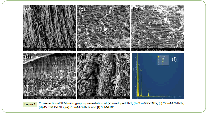
Figure 1: Cross-sectional SEM micrographs presentation of (a) un-doped TNT, (b) 9 mM C-TNTs, (c) 27 mM C-TNTs, (d) 45 mM C-TNTs, (e) 75 mM C-TNTs and (f) SEM-EDX.
The crystallographic structure of un-doped and C-TNTs nanotubes fabricated by a template-assisted sol-gel technique using titanium (IV) butoxide as precursor and oxalate anion as carbon doping agent are shown here in Figures 2. XRD diffractograms have revealed peaks at scattering angles of 25.49°, 38.11°, 48.14°, 54.58°, 63.00°, 70.33° and 75.66° belonging to the Anatase phase of TiO2 (JCPDS No. 21- 1272). It is also noticeable that the intensity of the dominate Anatase peak at 2θ angle of 25.62° belonging to the (101) diffraction plane had the highest intensity. This implies that the growth orientation of the un-doped and C-TNTs was in the (101) plane. Additionally, Figure 2 has also revealed the presence of a diffraction peak at 2θ angle of 40.6° for the undoped and C-TNTs samples belonging to the (202) diffraction plane of Brookite (JCPDS No. 29-1360 TiO2). Brookite formation as an impurity crystalline product has been cited in numerous publications [15-17]. It has been reported that the Brookite content in TiO2 nano-particles prepared by a sol-gel technique decrease with decrease in titanium precursor to water ratio (Tiprecursor/ H2O) from 1:4 to 1:7. In this work a lower Ti-precursor/ H20 ratio of 1:3 has been utilised. Our lower Ti-precursor/H2O might have catalyzed the formation of the Brookite phase in our samples [15,16]. Our XRD analysis has revealed that there are no other peaks for amorphous aluminium membrane templates and other impurities suggesting the high purity nature of our samples.
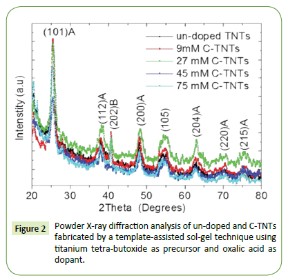
Figure 2: Powder X-ray diffraction analysis of un-doped and C-TNTs fabricated by a template-assisted sol-gel technique using titanium tetra-butoxide as precursor and oxalic acid as dopant.
Figure 2 has revealed that the peak width and Intensities of the diffraction peak of Anatase becomes narrower and the intensity increases as carbon dopant concentration increase. This implies an improvement in growth crystallinity as dopant concentrations increases.
The in-cooperation of C atoms in TiO2 lattice and influence of C doping on the TiO2 crystal structure was cross examined by closely monitoring behavior of the Anatase dominant peak at 25.49° belonging to the plane. Figure 3 shows the XRD peak shift dependence of carbon dopant concentration. It has been reported in literature that substitutional doping results in peak shifts to higher 2θ values, whereas interstitial doping results in XRD peak shifts to lower angles [8,9]. In our samples we have observed an initial sharp increase in peak position to higher 2θ values, which suggest the carbon atom where occupying the oxygen atom in the TiO2 structure which results in formation of a composite oxide of the structure TiO2(x-y) Cy (substitutional doping) for the two samples 9 mM C-TNTs and 27 mM C-TNTs.
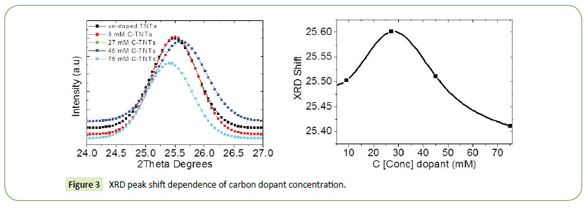
Figure 3: XRD peak shift dependence of carbon dopant concentration.
Further increase in C doping concentration above 27 mM resulted in a sharp decrease to lower 2θ values which suggested an additional interstitial carbon doping in our samples as shown here in Figure 3. However, we have observed a general decrease in XRD peak shift to lower 2θ values with increase in carbon doping concentration as evidenced here from Figure 3, this suggest interstitial doping was more pronounced in our samples. Hence, we can speculate that the in-cooperation of C into TiO2 lattice can be observed through XRD peak shifts of the most dominant Anatase peak to lower 2θ values.
 (1)
(1)
where d is the crystallite size, λ is the wavelength of the X-ray [Cu]kα=0.154 nm), θ is the diffraction angle of the dominate Anatase (101) peak, is the full width at half maximum (FWHM) in radians, and k is the shape factor with a value of 0.89. Based, on Bragg’s law (2dSinθ=λ) and a formula for tetragonal system,
 (2)
(2)
Where d is the inter-planar spacing, hkl are the miller indexes of a planes, a and c are the lattice parameters. The calculated lattice parameters for the un-doped and C-TNTs are presented here in Table 1.
| C-TNTs |
-101
d spacing (Å) |
Lattice parameters (Å) |
Crystallite size (nm) |
| a |
c |
| Bulk Anatase |
3.52 |
3.784 |
9.514 |
-- |
| un-doped TNTs |
3.4902 |
3.761 |
9.143 |
11.39 |
| 9 mM C-TNTs |
3.4889 |
3.769 |
9.197 |
11.43 |
| 27 mM C-TNTs |
3.4755 |
3.742 |
9.461 |
9.94 |
| 45 mM C-TNTs |
3.4876 |
3.752 |
9.809 |
10.03 |
| 75 mM C-TNTs |
3.5011 |
3.742 |
9.83 |
11.42 |
Table 1: Lattice parameters, d-spacing and crystallite size of un-doped and C-TNTs prepared by a template-assisted sol-gel technique.
The three most common polymorphs of titanium dioxide have the following lattice parameters: Anatase (a=3.784 Å, c= 9.514 Å, α=β=γ=90 PDF 78-2486) with d spacing of (101) plane of 3.52 Å) [10], Rutile (a=4. 593 Å, c=2.958 Å α=β=γ=90° PDF #89-8304) with a d-spacing of 3.25 Å) [11], Brookite (a=9.174 Å, b=5.449 Å, c=5. 138 Å, α=β=γ=90° PDF 76-1934) with d-spacing of 3.51 Å [12]. The calculated d-spacing of the as synthesized TNTs samples are presented in Table 1. All the calculated d-spacings are in agreement with standard values of the [101] Anatase TiO2 inter-planar distances. Therefore, it can be deduced that all these samples retained an Anatase crystal structure. The un-doped TNTs possess a d-spacing of 3.490 Å which slightly deviates from 3.520 Å of the bulk Anatase. Such a narrowed d-spacing indicates a contraction of the lattice in a particular direction [13].
It is has been reported that under stress or strain effects, the diffraction peaks get displaced and broadened [14]. In our powder patterns, a significant change in d-spacing is observed between the un-doped and 75 mM C-TNTs. The most intense plane of at a 2° angle of 25.49° was observed to be 3.4902 Å for un-doped TiO2. On doping, this d-spacing shows a shift to a 2° value of 25.41°, corresponding to a d-spacing 3.5011 Å for 75 mM C-TNTs. Since the displacement was not quite pronounced, we assume that strain induced by the carbon dopant is minimal.
The lattice constants “a” and “c” corresponding to the different atomic concentrations were calculated from [200] and [101] planes respectively. Table 1 show the variation of lattice parameters “a” and “c” as the dopant concentration increases. It is clearly evident that the lattice constant “a” along the basal planes remains more or less constant for all the synthesized TNTs. There are obvious changes in the lattice parameters c; as the dopant concentration increases compared to the un-doped Anatase TNTs. The lattice constant increases with the increase in carbon concentration along the c-axis only. The maximum elongation of c-axis is about 0.687 Å, from 9.143 Å (un-doped TNTs) to 9.830 Å (75 mM TNTs). The elongation of the lattice constants “c” confirms the successful introduction of carbon in the TiO2 lattice. Moreover, the elongation of the lattice constants “c” also suggest the possibility carbon substituting oxygen sites because of the large differences in ionic radii between the dopant ions [15]. The effective ionic radii of carbon and oxygen are 0.77 Å and 0.65 Å respectively. Therefore, any substitution of a carbon for oxygen in the TiO2 lattice would introduce a distortion and change in lattice distances.
Since only, the “c” dimension is changing, whilst the ‘a” remains constant for the range of dopant concentration studied. It can be speculated that substitution doping of carbon atoms for oxygen atoms is preferentially taking place on the face centered lattice sites in the Anatase TNTs structure. Also, the consistent increase in the lattice parameter values of the c-axis with the increase in carbon dopant concentration is also evidence of successful incorporation of carbon atom in the titanium dioxide lattice. This result is in mutual agreement with our previous analysis in Figure 3, where we observed general shift in XRD peak positions to lower 2° values with an increase in carbon dopant concentration [16]. The calculated crystallite sizes from equation 1, illustrated here in Table 1 are 11.39 nm, 11.43 nm, 9.94 nm, 10.03 nm and 11.42 nm for the un-doped TNTs, 9 mM C-TNTs, 27 mM C-TNTs, 45 mM C-TNTs and 75 mM C-TNTs respectively. In our case XRD analysis has revealed that the in-cooperation of carbon into TiO2 matrix resulted in an insignificant change in grain crystallite size. The insignificant change in crystallite size suggests that doping TiO2 with carbon greatly suppresses crystalline growth of TNTs. This observation is mutual agreement with calculated d spacing, which did not show any significant change with increase in doping concentration. This might be due to the fact that the oxalate anion(COO)2 in aqueous solution can be surrounded by hydrated water molecules (H2δ+Oδ-) due ion-dipole interaction, the diffusion into TiO2 matrix can be restricted. As a result of limited diffusion a layer composed of carbonate species forms on the surface of the nano-crystals resulting in the suppression of TiO2 crystal growth size [16-22].
Background Raman Spectroscopy
It is well known that the Anatase TiO2 is characterized by the tetragonal space group D194h (I4/amd) with titanium cations sixfold coordinated to oxygen anions, forming distorted octahedral edges. The primitive unit cell has two TiO2 units with Ti atoms (0, 0, 0) and (0, 1/2, 1/4) and O atoms at (0, 0, u), (0, 0, ?), (0, 1/2, u +1/4) and (0, 1/2, 1/2-u), giving rise to six active Raman modes: A1g+2B1g+3Eg. Anatase phase of TiO2 has vibrational modes at of Raman frequencies and symmetry at 144 cm−1 (Eg1), 197 cm−1 (Eg2), 399 cm−1 (B1g), 513 cm−1 (A1g), 519 cm−1 (B1g), and 639 cm−1 (Eg3) [23,24]. The Rutile structure is characterized by the tetragonal space group of P42/mnm and five active modes (B1g, multi-proton process, Eg, A1g, and B2g) appearing at 143 cm−1 (B1g), 236 cm−1 multi-proton process, 447 cm−1 (Eg), 613 cm−1 (A1g), and 826 cm-1 (B2g). Rutile titanium cations are sixfold coordinated to oxygen anions, forming distorted octahedral joined by sharing the octahedral edges. Brookite phase of TiO2 belongs to the Pbca space group, its lower symmetry and larger unit cell results in a larger number of Raman active phonons compared to Anatase and Rutile structures. From the symmetry considerations one can expect 36 (9A1g+9 B2g+9B3g) [25].
Confocal Raman spectroscopy: Surface analysis
Figures 4a-4g shows the confocal Raman Large Area Scan (LAS) of un-doped titanium dioxide nanotubes prepared by a template assisted sol gel technique. Confocal Raman Imaging LAS was performed in sample area of 500μm ? 500 shown in Figures 4a and 4b. The results of basis analysis of are shown in Figures 4c-4e. The combined color coded images of three differently crystallized phases of TiO2 are shown here in Figure 4f and the corresponding spectra is shown here in Figure 4g. Raman Single spectra (RSS) acquired on the blue and red crosses in Figure 4a are shown in Figure 4b. RSS of the un-doped TNTs prepared by a template assisted sol-gel technique have revealed Raman vibrational modes at 153.19 cm−1 (Eg-A), 205.62 cm−1(Eg-A), 328.33 cm−1(B1g-B) 404.55 cm−1 (B1g-A) 523.26 cm−1 (A1g-A), 523.26 cm−1 (B1g-A) and 648.69 cm−1(Eg-A) belonging to a mixed Anatase- Brookite phases. This observation is in mutual agreement with XRD analysis which revealed the presence of Brookite diffraction peak at 2θ angle of 40.6°. The presence of Brookite phase of titanium in our samples might be attributed to low titanium precursor/water ratio of 1:3 [15-17] Additionally it has been reported that the thermodynamically stable of either Anatase and/or Brookite exist when the crystallite sizes are about 11 nm for Anatase and about 11-35 nm for the Brookite phase. Whilst the Rutile phase is predominately thermodynamically stable in crystallite sizes above 35 nm. Our confocal Raman LAS has revealed that the majority of the sample as depicted by sum of maroon–yellow area consists of a mixed Anatase-Brookite phase which is mutual agreement with XRD analysis which revealed a crystallite size of 11.39 nm [26].
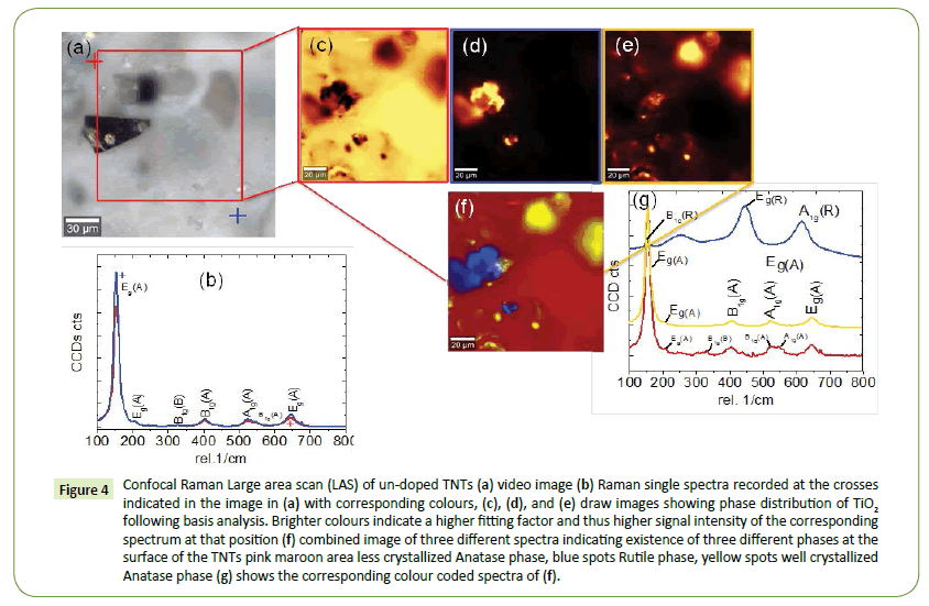
Figure 4: Confocal Raman Large area scan (LAS) of un-doped TNTs (a) video image (b) Raman single spectra recorded at the crosses indicated in the image in (a) with corresponding colours, (c), (d), and (e) draw images showing phase distribution of TiO2 following basis analysis. Brighter colours indicate a higher fitting factor and thus higher signal intensity of the corresponding spectrum at that position (f) combined image of three different spectra indicating existence of three different phases at the surface of the TNTs pink maroon area less crystallized Anatase phase, blue spots Rutile phase, yellow spots well crystallized Anatase phase (g) shows the corresponding colour coded spectra of (f).
To obtain a conclusive crystalline phase distribution, a LAS was performed on the video image in Figure 4a. Confocal Raman imaging LAS scan was performed on the highlighted rectangular area 330 μm × 330 μm shown here in Figure 4a. Figure 4f shows the combined color-coded image reveals the distribution of about 3 distinct crystalline phases of TiO2 and Figure 4g corresponding color-coded spectra of the 3 distinct phases of TiO2. The majority of the un-doped TNTs sample depicted by the maroon area in Figure 4f, with corresponding maroon Raman spectra, has revealed Raman vibration modes at 153.78 cm−1 (Eg-A), 209.08 cm−1 (Eg-A), 331.04 cm−1 (B1g-B), 403.74 cm−1 (B1g-A), 527.16 cm−1 (A1g-A), 541.83 cm−1 (B1g-A) and 644.59 cm−1(Eg-A) which consist of Anatase phase of TiO2 The lowest Eg1-Anatase mode of the maroon area which is dominant in the un-doped TNT sample has been red shifted by Δ9. 78 cm−1 whereas the highest Eg3- Anatase mode has been blue shifted by Δ3. 59 cm−1 compared to the vibrational frequencies the bulk TiO2. The significant shift is attributed to phonon confinement and decrease in particle size. Additionally, Figure 4f has revealed that the surface of the un-doped TNTs has blue spots with corresponding blue Raman spectra shown here in Figure 4g. The blue spots have Raman vibrational frequencies at 150.64 cm−1 (B1g-R), 252.14 cm−1 (mutliphonon process), 447.42 cm−1 (Eg-R) and 616.09 cm-1 (A1g-R) all belonging to a Rutile phase of TiO2. Whilst the yellow spots, Figure 4f have Raman spectra with Raman vibrational modes at 153.78 cm−1 (Eg-A), 204.72 cm−1 (Eg-A), 332.27 cm−1(B1g-B), 521.59 cm−1 (B1g-A), 545.51 cm−1 (A1g-A), and 644.57 cm−1 (Eg-A) all belonging to a Anatase and Brookite mixed phase. Confocal Raman Large area scan of un-doped TNTs prepared by a template assisted sol-gel technique have revealed for the first time that the surface of the nanotubes consists of Anatase, Brookite and Rutile phases of TiO2. The un-controlled nature of formation and co-existence of these three phases in TNTs membranes might be the main reason why DSSC based on TNTs anodes still have lower efficiency as compared to the TiO2 nanoparticle counterpart.
These results in mutual agreement with XRD measurements of the un-doped TNTs sample that revealed peaks at 25.62° (101), 38.33° (112), 40.6° (202), 48.40° (200), 54.9° (105), 62.5° (118), 70.7° (220), and 75.1° (215) belonging to mixed Anatase-Brookite phase as shown here in Figure 2. However, no additional peaks due Rutile phase of TiO2 have been detected through XRD measurements. Our confocal Raman LAS measurements have revealed the presence of Rutile phase in our samples. Our method of characterization of TNTs through confocal Raman LAS has outperformed XRD measurements which failed to detect the presence of the Rutile phase in the un-doped TNTs samples.
Figures 5a-5f shows the Raman LAS of the 9 mM C-TNTs prepared by template-assisted sol-gel technique. The blue and red RSS recorded, are linked to positions indicated in Figure 5a by the blue and red crosses. RSS in Figure 5b has revealed.
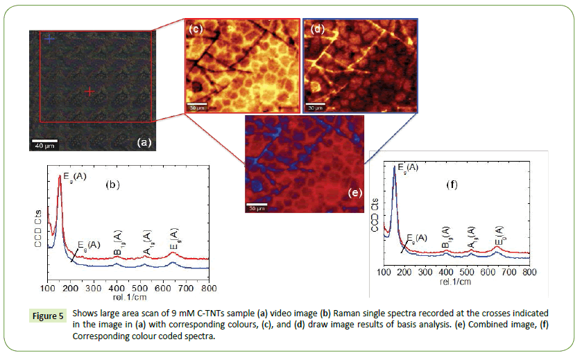
Figure 5: Shows large area scan of 9 mM C-TNTs sample (a) video image (b) Raman single spectra recorded at the crosses indicated in the image in (a) with corresponding colours, (c), and (d) draw image results of basis analysis. (e) Combined image, (f) Corresponding colour coded spectra.
Raman vibrational modes at 154.25 cm−1 (Eg-A), 208.11 cm−1 (Eg- A), 327.53 (B1g-B) 403.43 cm−1 (B1g-A) 527.91 cm−1 (A1g-A) and 645.49 cm−1 (Eg-A) consisting of a mixed Anatase and Brookite phase. Confocal Raman LAS measurements have revealed that the majority of the sample as depicted by the red area in Figure 5e consist of a mixed Anatase-Brookite phase with Raman vibrational modes 154.68 cm−1(Eg-A), 207.33 cm−1 (Eg-A), 331.92 cm−1 (B1g-B), 403.09 cm−1(B1g-A) 529. 66 cm−1 (B1g-A), 546.32 cm−1 (A1g-A) and 644.54 cm−1 (Eg-A). Additionally the blue area in Figure 5e have revealed a Raman spectra with vibrational modes at 153.67 cm−1 (Eg-A), 205.59 cm−1 (Eg-A), 404.55 cm−1(B1g) 547.96 cm−1 (A1g) and 645.66 cm−1(Eg) with an Anatase phase only [27,28]. It is noticeable that introduction of carbon dopant seems to foster formation of a mixed Anatase-Brookite phase [29]. This is probably that the due to the fact that the nucleation and growth mechanism of rutile are destructively affected by the introduction of the carbon dopant in crystalline lattice [27-29] It is also noticeable that the introduction of the carbon dopant the Raman spectra tapered significantly and the corresponding peak intensities increased. This implies that the crystallinity of the Anatase-Rutile phase was greatly enhanced by doping with carbon atoms. This observation is in mutual agreement with XRD analysis that have revealed an increase in peak intensity and narrowing of peaks with increase in carbon dopant concentration as illustrated here in Figure 3. Additionally, our confocal Raman LAS measurements have revealed that the 9 mM C-TNTs do not have Rutile phase TiO2. The disappearance of the Rutile phase might be due to introduction in TiO2 matrix which in turn inhibited formation of Rutile phase. Additionally, our confocal Raman LAS measurements have revealed the presence of a Brookite phase of TiO2 with a Raman peak at 331.92 cm−1. This observation is in mutual agreement with XRD measurements which also confirmed the presence of the Brookite peak in the 9 mM C-TNTs.
To further investigate effect of doping on TiO2 crystalline phase distribution, confocal Raman LAS was performed on the 27 mM C-TNTs and 75 mM C-TNTs samples as shown here in Figures 6a- 6f and Figures 7a-7f respectively. Figure 6 shows the Confocal Raman LAS of 27 mM C-TNTs samples. RSS in Figure 6a has revealed Raman vibrational modes at 153.17 cm−1 (Eg-A), 202.98 cm−1 (Eg-A), 399.63 cm−1 (B1g-A), 521. 19 cm−1 (A1g-A) and 644.19 cm−1 (Eg-A) all belonging to the Anatase phase of TiO2. Confocal Raman large area scan presented here in Figure 6e has revealed the presence of two differently crystallized Anatase phases with Raman vibration modes at 151.07 cm−1 (Eg-A), 201.25 cm−1 (Eg-A), 398.93 cm−1 (B1g-A), 519.73 cm−1 (A1g-A), and 642. 14 cm−1 (Eg-A) all belonging to Anatase phase.
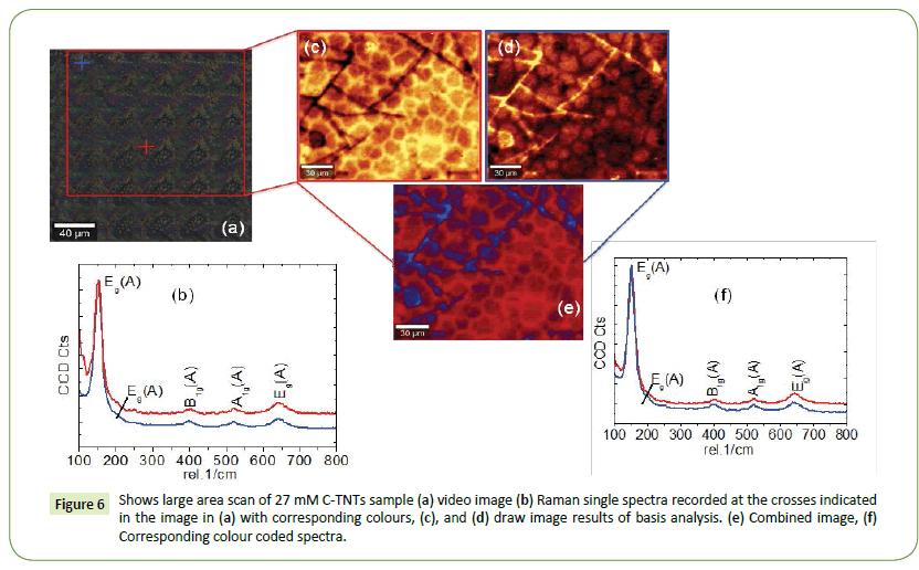
Figure 6: Shows large area scan of 9 mM C-TNTs sample (a) video image (b) Raman single spectra recorded at the crosses indicated in the image in (a) with corresponding colours, (c), and (d) draw image results of basis analysis. (e) Combined image, (f) Corresponding colour coded spectra.
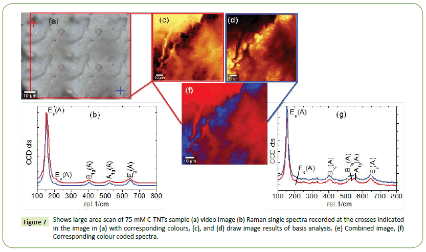
Figure 7: Shows large area scan of 75 mM C-TNTs sample (a) video image (b) Raman single spectra recorded at the crosses indicated in the image in (a) with corresponding colours, (c), and (d) draw image results of basis analysis. (e) Combined image, (f) Corresponding colour coded spectra.
The depth profiling was done using a similar procedure as LAS. Depth profiles were collected by employing the XZ-scan mode along the z-axis of the nanotubes as shown in Figures 8a-8f. Confocal Raman depth profiling was performed in the sample area marked by a red line in Figure 8a. Figure 8b shows RSS recorded on the blue and red cross on the stitching image in Figure 8a. RSS the blue and red cross have revealed that the sample consists of a mixed Anatase-Brookite phase with Raman modes at 153.39 cm−1 (Eg1-Anatase), 204.91 cm−1 (Eg2-Anatase), 329 cm−1 (B1g-Brookite), 404.14 cm−1(B1g-Anatase), 526.76 cm−1 (A1g-Anatase), 549.96 cm−1 (B1g-Anatase) and 648.07 cm−1 (Eg3-Anatase). This observation is in mutual agreement with confocal Raman large area scan shown here in Figure 4 which have revealed the presence of a mixed Anatase and Brookite phase. The Rutile phase of the un-doped sample was not detected through the use of the depth profiling which suggests that the Rutile phase of the un-doped TiO2 was only present on the surface of the sample. We can safely say that confocal Raman spectroscopy was successfully used to evaluate the crystalline phase composition of TNTs on the surface (XZ) and along the tubes (XZ) via depth profiling and our method of measurements have outperformed RSS spectra and XRD analysis which do not conclusive crystalline phase distribution in TNTs. This information could prove to be vital for the development of efficient electrode materials consisting of non-metal doped TNTs for development of solar cells.
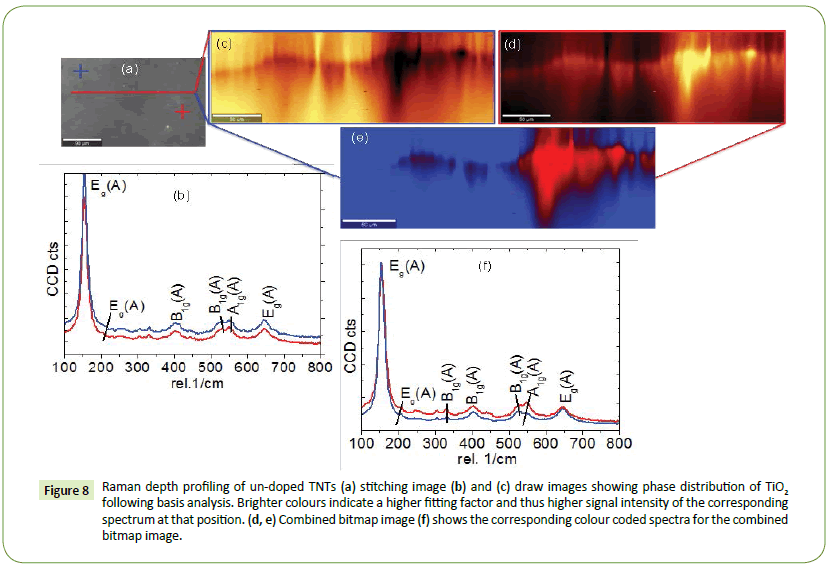
Figure 8: Raman depth profiling of un-doped TNTs (a) stitching image (b) and (c) draw images showing phase distribution of TiO2 following basis analysis. Brighter colours indicate a higher fitting factor and thus higher signal intensity of the corresponding spectrum at that position. (d, e) Combined bitmap image (f) shows the corresponding colour coded spectra for the combined bitmap image.
Conclusion
XRD analysis have revealed peaks at 2θ angles of 25.49°, 38.11°, 48.14°, 54.58°, 63.00°, 70.33° and 75.66° belonging to the Anatase phase of TiO2. Additionally, XRD analysis has revealed an additional peak 2θ angle of 40.6° for the un-doped and C-TNTs samples belonging to the (202) diffraction plane of Brookite. The presence of Brookite phase has been is due to the Ti-precursor/ H2O water ration 1:3. Our lower Ti-precursor/H2O might have catalysed the formation of the Brookite phase in our samples. Moreover, the in-cooperation of C atoms in TiO2 lattice and influence of C doping on the TiO2 crystal structure was cross examined by closely monitoring by change in lattice parameters “a” and “c” calculated from [200] and [101] planes respectively. Our analysis has revealed that there was no significant change in the lattice constant “a”. However, we have observed significant change in lattice parameters c; as the dopant which can be correlated to carbon dopant concentration. The change is lattice parameter “c” confirmed carbon doping into TiO2 matrix, which is beneficial for solar cell applications. Large area Confocal Raman analysis have revealed a mixed Anatase, Brookite and Rutile phase at the surface of un-doped TNTs. Our method of characterization of TNTs through confocal Raman LAS has outperformed XRD measurements which failed to detect the presence of the Rutile phase in the un-doped TNTs samples. Moreover, Confocal Raman LAS have revealed that introduction of carbon into TNTs sample prompted the formation of a mixed Anatase and Brookite phase whilst it inhibited the formation of Rutile phase of TiO2 in our C-TNTs samples. Additionally, we performed confocal Raman depth profiling in the XZ direction and our analysis have revealed the presence of a Mixed Anatase and Brookite phase of TiO2.
In conclusion in this work we have successfully employed Confocal Raman Spectroscopy coupled with Raman imaging for the first time to successful mapping out crystalline phase composition of un-doped and C-TNTs. This technique proved to be handy as sample measurements were done on large area without the need for sophisticated sample preparation. Such a technique can be adopted to evaluate the crystalline composition of TiO2 on an industrial scale. More particularly in fabrication of DSSC employing TNTs substrates.
Acknowledgements
We are grateful for financial support from our sponsors’ South African National research foundation (NRF), Govan Mbeki Research and Development Centre (GMRDC) of the University of Fort Hare and Sasol Inzalo Foundation. The authors would also like to acknowledge the DST/CSIR Nanotechnology Innovation Centre, National Metrology Institute of South Africa Materials laboratory and for of the TiO2 nanotubes samples.
References
- Krysa J, Lee K, Pausova S, Kment S, Hubicka Z, et al. (2017) Self-organized transparent 1D TiO2 nanotubular photoelectrodes grown by anodization of sputtered and evaporated Ti layers: A comparative photoelectrochemical study. Chem Eng J 308: 745-753.
- Dubey M, He H (2012) Centre for advanced photovoltaics. Scanning electron microscopy, Dr. Viacheslav Kazmiruk (ed), In Tech.
- Lupiwana M, Taziwa R, Meyer E, Katwire D (2017) Structural, morphological, topographical characterization of titanium dioxide nanotubes metal substrates for solar cell application. J Mater Sci Technol 3: 17-31.
- Neupane MP, Il SP, Bae TS, Lee MH (2013) Sonochemical assisted synthesis of nano-structured titanium oxide by anodic oxidation. J Alloys Compd 581: 418-422.
- Dong B, He BL, Chai YM, Liu CG (2010) Novel Pt nanoclusters/titanium dioxide nanotubes composites for hydrazine oxidation. Mater Chem Phys 120: 404-408.
- Zhang M, Bando Y, Wada K (2001) Synthesis of coaxial nanotubes: Titanium oxide sheathed with silicon oxide. Mater Sci 16: 1408-1412.
- Indira K, Mudali UK, Nishimura T, Rajendran N (2015) Development of self-assembled titania nanopore arrays for orthopedic applications. Journal of Bio- and Tribo-Corrosion 3: 1.
- Prikrylová K, Drbohlavová J, Svatoš V, Gablech V, Kalina L, et al. (2016) Fabrication of highly ordered short free-standing titania nanotubes. Monatsh Chem 147: 943-949.
- Scanlon DO, Dunnill CW, Buckeridge J, Shevlin SA, Logsdail AJ, et al. (2013) Band alignment of rutile and anatase TiO2. Nature Mater 12: 798-801.
- Taziwa R, Meyer E (2014) Carbon doped nano-crystalline TiO2 photo-active thin film for solid state photochemical solar cells. ANP 3: 54-63.
- Ahmad A, Buzby S, Ni C, Ismat SS (2008) Effect of Nb and Sc doping on the phase transformation of sol-gel processed TiO2 nanoparticles. J Nanosci Nanotechnology 8: 2410-2418.
- Bu X, Zhang G, Zhang C (2012) Effect of nitrogen doping on anatase-rutile phase transformation of TiO2. Appl Surf Sci 258: 7997-8001.
- Liu H, Yu L, Chen W, Li Y (2012) The progress of nanocrystals doped with rare earth ions. J Nanomater 2012: 1-9.
- Martin J, Maiz J, Sacristan J, Mijangos C (2012) Tailored polymer-based nanorods and nanotubes by "template synthesis": From preparation to applications. Polym 53: 1149-1166.
- Lu X, Mou X, Wu J, Zhang D, Zhang L, et al. (2010) Improved-performance dye-sensitized solar cells using Nb-doped TiO2 electrodes: Efficient electron injection and transfer. Adv Funct Mater 20: 509-515.
- Zhang Q, Lian G (2003) Preparation of oxide nanocrystals with tunable morphologies by the moderate hydrothermal method: Insights from Rutile TiO2. Langmuir 19: 967-971.
- Isley SL, Penn RL (2006) Relative brookite and anatase content in sol-gel-synthesized titanium dioxide nanoparticles. J Phys Chem B 110: 15134-15139.
- Meagher EP, Lager GA (1979) Polyhedral thermal expansion in the TiO2, polymorphs: Refinement of the crystal structures of rutile and brookite at high temperature. Can Mineral 17: 77-85.
- Bersani D, Lottici PP, Ding XZ (1998) Phonon confinement effects in the Raman scattering by TiO2 nanocrystals. Appl Phys Lett 72: 73-75.
- Raja KS, Misra M (2011) Iron oxide nanotubes incorporated with fluoride anions for enhanced Li-ion intercalation. ECS transactions 33: 15-24.
- Devi G, Muthy N, Kumar GS (2010) Photocatalytic activity of TiO2 doped with Zn 2+ and V 5+ transition metal ions: Influence of crystallite size and dopant electronic configuration on photocatalytic activity. Mater Sci Eng B 166: 1-6.
- Burns A, Hayes G, Li W, Hirvonen J, Demaree DJ, et al. (2005) Neodymium ion dopant effects on the phase transformation in sol-gel derived titania nanostructures. Mater Sci Eng B 111: 150-155.
- Balachandran U, Eror NG (1982) Raman spectra of titanium dioxide. J Solid State Chem 42: 276-282.
- Taziwa R, Meyer EL, Chinyama KG (2012) Raman temperature dependence analysis of carbon-doped titanium dioxide nanoparticles synthesized by ultrasonic spray pyrolysis technique. J Mater Sci 47: 1531-1540.
- Tompsett GA, Bowmaker GA, Cooney RP, Metson JB, Rodgers KA, et al. (1995) The Raman spectrum of brookite, TiO2 (Pbca, Z=8). J Raman Spectrosc 26: 57-62.
- Kumar SG, Rao KSRK (2014) Polymorphic phase transition among the titania crystal structures using a solution-based approach: from precursor chemistry to nucleation process. Nanoscale 6: 11574-11632.
- Ogacho AA, Ajuoga P, Aduda BO (2015) Suppression of anatase to rutile phase transformation of niobium doped TiO2 synthesized by high temperature diffusion technique. Int J Innovation Edu Res 3: 140-146.
- Hanaor DAH, Sorrell CC (2011) Review of the anatase to rutile phase transformation. J Mater Sci 46: 855-874.
- Arnal P, Corriu JR, Leclercq D, Mutin HP, Vioux A (1996) Preparation of anatase, brookite and rutile at low temperature by non-hydrolytic sol–gel methods. J Mater Chem 6: 1925-1932.


 (1)
(1) (2)
(2)


